Interfaces and hardware assembly
Main components
3DV-EdgeAI-32 consists of two boards: the TRSU.469555.001 carrier board and the TRSU.467475.001 processor module.
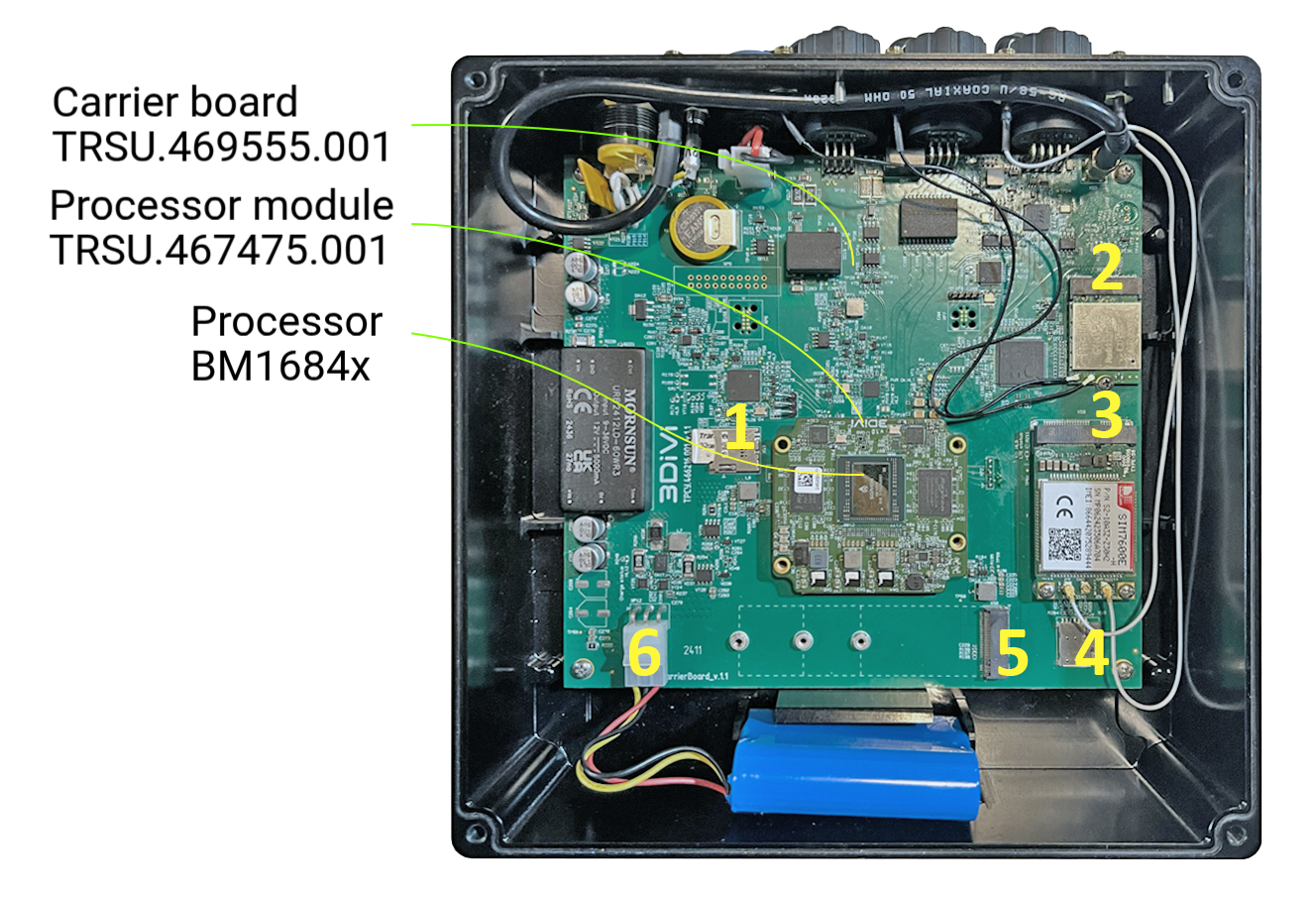
- MicroSD slot;
- M.2 slot for WiFi-Bluetooth module;
- LTE module slot;
- MicroSIM slot;
- M.2 slot for NVME (for connecting a drive or other boards);
- Battery connector.
Power supply connection
The device must be powered externally from a DC source with a voltage of 9 to 27 V. The power consumption (under load) for a 12 V supply is up to 5 A.
Connect a suitable DC source to the power connector: the red wire is "+" and the black wire is "-".
Interfaces
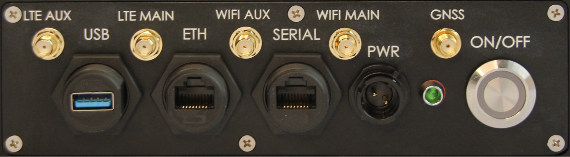
Location of interfaces on the front panel of the device (from left to right):
LTE AUX: SMA connector for connecting an auxiliary antenna of the 3G/LTE/4G module. Used to connect an external antenna if the device is equipped with the corresponding optional 3G/LTE/4G module (M.2 key B connector).
LTE MAIN: SMA connector for connecting the main antenna of the 3G/LTE/4G module. Used to connect an external antenna if the device is equipped with the corresponding optional 3G/LTE/4G module (M.2 key B connector).
WIFI AUX: SMA connector for connecting the auxiliary antenna of the WiFi-Bluetooth module. Used to connect an external antenna if the device is equipped with the corresponding optional module (M.2 key A+E).
WIFI MAIN: SMA connector for connecting the main antenna of the WiFi-Bluetooth module. Used to connect an external antenna if the device is equipped with the corresponding optional module (M.2 key A+E).
GNSS: SMA connector for connecting the external antenna of the GLONASS/GPS module (included with the device). The device supports active GNSS antennas.
USB: 1 USB 3.0 port for connecting external devices.
ETH: 1 Ethernet port supporting data transfer rates of up to 1000 Mbps.
SERIAL: RG-45 connector plug for connecting RS-232, RS-485, and CAN interfaces. The interface pinout is shown below:

PWR: Power connector socket for connecting an external power supply with a voltage range of 9 to 36 VDC. Power consumption at 12 V is up to 4 A. To connect an external power supply, you will need a plug (included in the package; red wire +, black -).
Bi-color Indicator: A bi-color indicator (red/green) is located to the right of the connector to display the device's operating modes.
ON/OFF: Power button.
Disassembly and assembly
Disassembly
To access the motherboard and compute module, turn off the power and wait until the LED goes out. Loosen the four screws securing the top cover and, using a gentle pry, lift the cover on one side.
The cover is sealed directly to the processor on the compute module through a layer of thermal paste and can be removed with a little force.
After removing the cover, disconnect the internal battery connector to completely disconnect the components.
Assembly
Before assembly, ensure that the processor has sufficient thermal paste applied to ensure proper heat transfer to the case. Remember that the processor on the compute module is not protected by an external heatsink and can be easily damaged by uneven loads or rough physical impact.
Assembly procedure:
Connect the internal battery connector.
Align the tab on the cover with the groove on the case.
Place the four screws into the slots on the cover.
Tighten the screws alternately, crosswise, several times, avoiding the cover from tilting to any side. The cover is directly adjacent to the processor and can damage it if tilted.
Ensure that the gap at the corners between the cover and the case remains approximately equal on all four sides.